

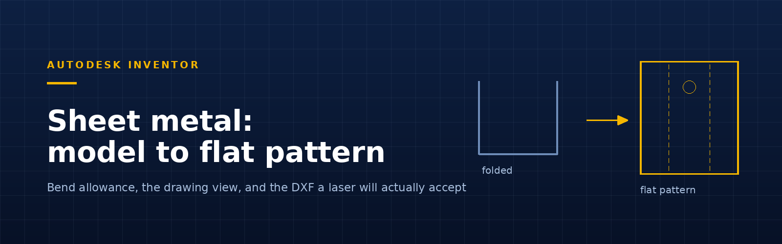
Short answer: to get an Inventor sheet metal flat pattern to the laser, create the flat pattern in the part, check the bend allowance your shop actually uses, then export it with Export Face As. If that crashes on a heavily detailed part, put the flat pattern on a sheet at 1:1 and export that instead. The step that goes wrong is almost never the export — it is the bend allowance nobody verified.
A flat pattern looks like a solved problem. You model the part, Inventor unfolds it, you send a DXF, parts come back.
Then one day a batch comes back 1.8 mm short across a bend, and you discover the K-factor in your sheet metal rule has been the Inventor default since 2019 while the shop has been pressing to a different one the whole time.
So here is the whole path, in the order it actually matters.
1. Model it as sheet metal, not as a thin solid
Only a sheet metal part can be unfolded. If the file was started from the standard part template and given a 2 mm extrude, Inventor has no idea it is sheet metal and there is nothing to flatten.
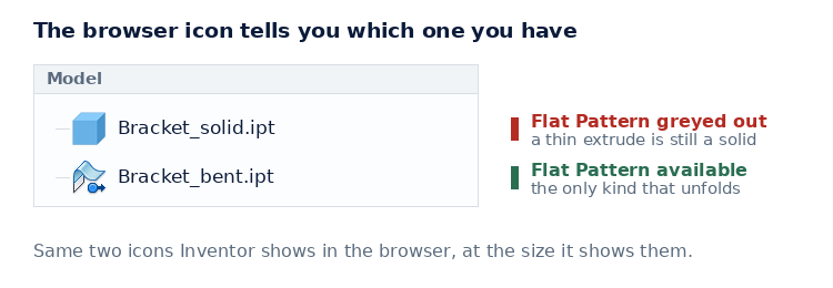
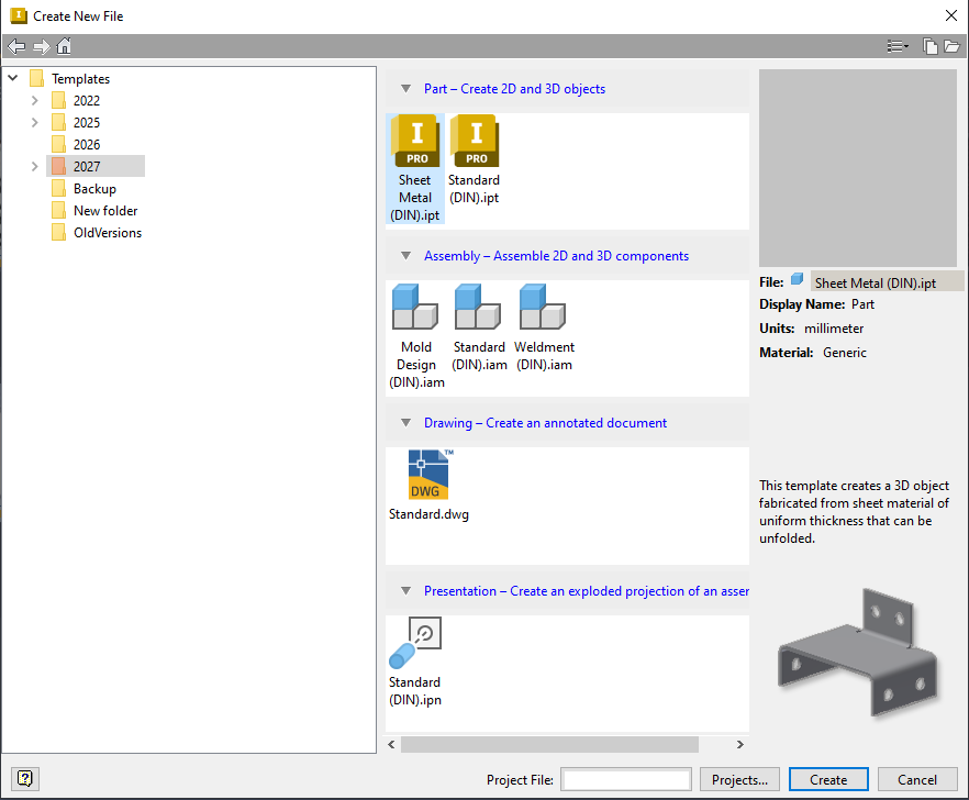
Start from the Sheet Metal template, or convert an existing part with Convert to Sheet Metal. Everything downstream depends on this, and it is the most common reason the Create Flat Pattern button is greyed out.

2. Set the sheet metal rule — this is the step that costs money
The Sheet Metal Rule holds thickness, material, bend radius and the unfold rule (K-factor, bend table or a custom equation). It decides the developed length, which decides whether the part fits.
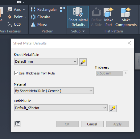
Default_mm and Default_KFactor are Inventor’s defaults — not your fabricator’s.Two things worth doing once, properly:
- Ask your fabricator what they actually press to, and encode that as a named rule per material and thickness. “Default_mm” is not an answer to a manufacturing question.
- Put the rules in a shared style library, not in each part, so one person’s correction reaches everybody.
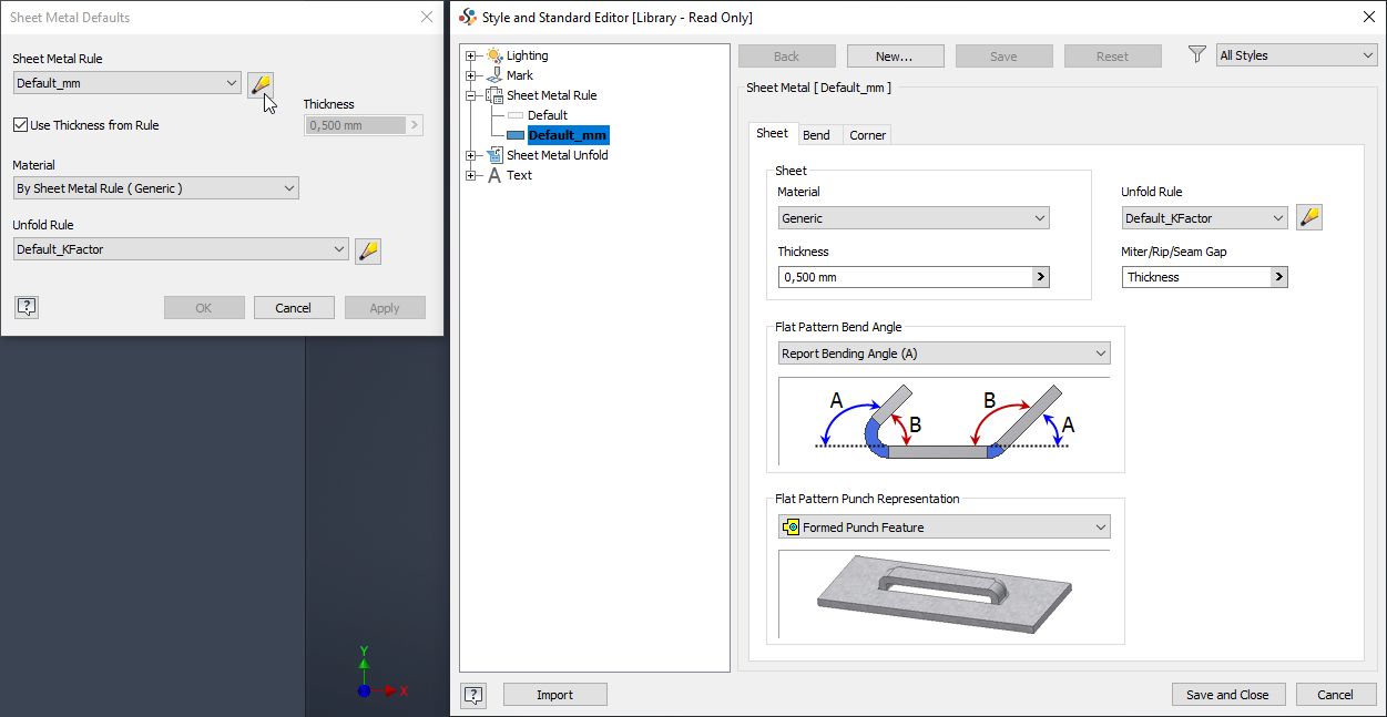
Autodesk’s background reading on sheet metal flat patterns covers how the unfold rule feeds the calculation.
3. Create the Inventor sheet metal flat pattern
On the Sheet Metal tab, Create Flat Pattern. Inventor unfolds the model and adds a Flat Pattern node to the browser, which you can reopen, edit and re-orient at any time. Autodesk’s page on working with flat patterns covers the editing commands.
Two things to check before it goes anywhere:
- Punch and grain direction. Inventor picks an orientation; your shop may need a specific one. Set it deliberately rather than accepting whichever face happened to face up.
- The A-side. If the part has a finished face, make sure the flat is the way round the fabricator expects, or you will get a mirrored part that is technically correct and practically useless.
4. Put the flat pattern on the drawing
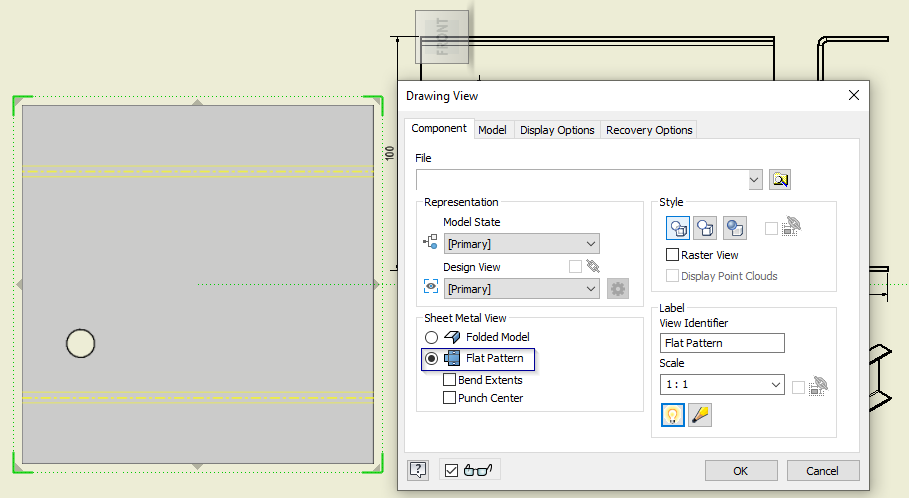
In the drawing, place a Base View and set the Sheet Metal View option to Flat Pattern rather than Folded Model. That gives you a proper documented view you can dimension, with bend lines and bend notes available as annotations. Autodesk’s step-by-step is creating a flat pattern drawing view.
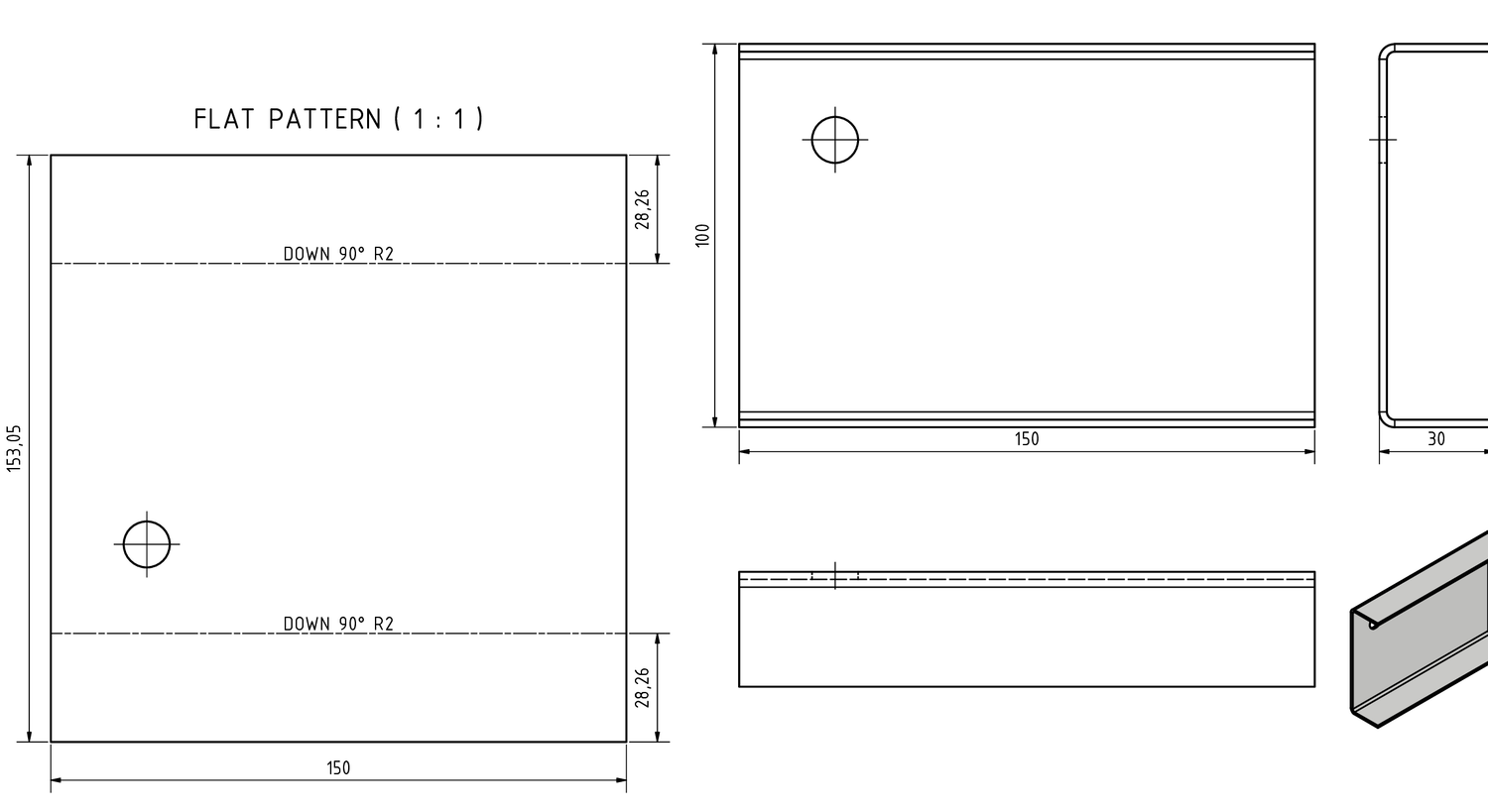
Include the bend notes. A DXF alone tells the press operator the outline; the bend notes tell them the sequence and direction, and their absence is why you get phone calls.
5. Export the DXF
There are two routes, and they are not equivalent.
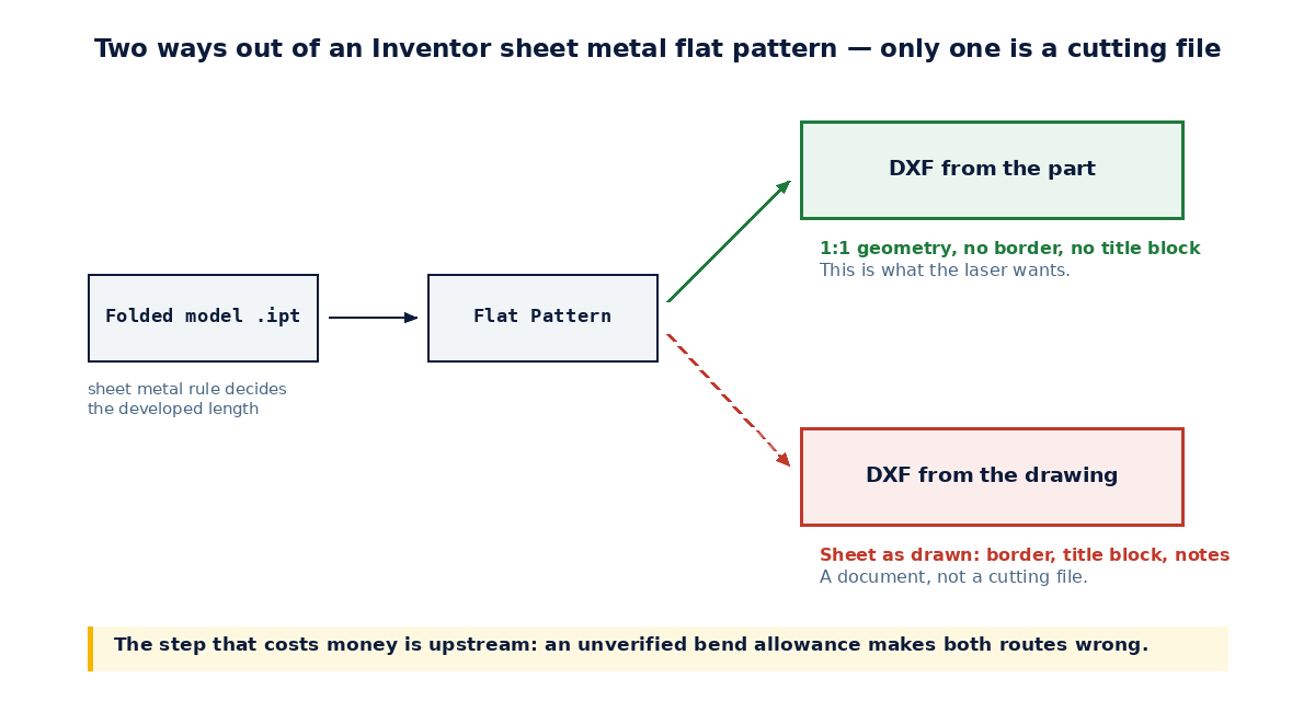
From the part — this is the one you want. Open the flat pattern, right-click the flat pattern face, and choose Export Face As…. Note that it is the face you right-click, not the Flat Pattern node in the browser.
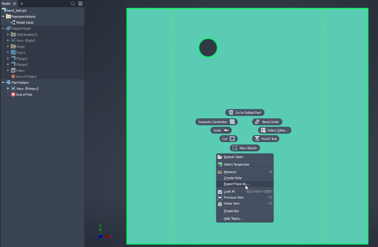
This is the command built for the job, and it does more than save a copy. Autodesk’s notes on exporting faces and flat patterns spell out why it matters: it moves all geometry to positive coordinates and converts the outer profile to a polyline — which is exactly what a lot of cutting equipment needs in order to consume a DXF directly. A file that opens fine in a CAD viewer can still be rejected by the machine for want of that.
From the drawing: Save Copy As → DXF exports the sheet as drawn, including borders, title block and annotations. As a general rule that is a document rather than a cutting file — but it is also the fallback when the first route will not run, which is the next section.
Set your layer mapping once, so bend lines and outlines land on the layers your fabricator expects. Getting this right is the difference between a file that runs and a file that gets emailed back.
When Export Face As fails
Export Face As is not bulletproof. On a very detailed flat pattern — dense punch features, many small cut-outs, a lot of loops on the one face — the export can fall over, and Inventor can take the session with it. It is not a licensing or a settings problem; the command is simply doing a lot of work on one face.
The workaround that holds up: put the flat pattern on a drawing sheet as a view at 1:1, and export that to DXF. It is the same Drawing View dialog from step 4 — Flat Pattern selected, and this time the Scale field left at 1:1 rather than whatever fits the sheet.
The scale is the whole point. At 1:1 the geometry on the sheet is the geometry of the part, so the DXF the machine receives is dimensionally correct — which is the one thing that actually matters. You then clean up what the sheet brings with it: use a plain sheet with no border or title block, or delete them before exporting, and keep annotations off the exported layers. That is a couple of minutes of work, and it beats a route that crashes.
So the honest ordering is: Export Face As first, because it gives you the polyline geometry without any cleanup. The 1:1 drawing view second, when the part is too heavy for it.
Where this stops scaling
Everything above is fine for one part. The pain arrives with an assembly of forty sheet metal parts, each needing a flat pattern, a drawing, a DXF and a line on a cutting list — and needing all of it again after a design change.
That repetition is what our Sheet Metal Drawing Creator handles: it walks the assembly, creates the 2D drawings from your existing template, exports DXF files of the flat patterns ready for manufacturing, exports STEP files of the assembly and individual parts, and builds an Excel parts list that includes each part’s flat pattern size — which is what you need to order material rather than guess at it. It runs on Autodesk Inventor 2021–2026.
If your sheet metal parts sit inside mixed assemblies rather than in a sheet-metal-only project, the Automatic Drawing Creator is the broader tool: it draws parts and assemblies of every kind, and places flat-pattern views with bend notes when the part happens to be sheet metal. SMDC is the specialist; ADC is the generalist that also handles this.
What neither does is decide your bend allowance. No tool can. Steps 1 and 2 are still yours, and they are still the ones that determine whether the parts fit.
Both carry a 15-day free trial, so you can run them against a real assembly before deciding — see the add-ins.